IR Drop Analysis#
The IR Drop Analysis module in OpenROAD (psm) is based on PDNSim,
an open-source static IR analyzer.
Features:
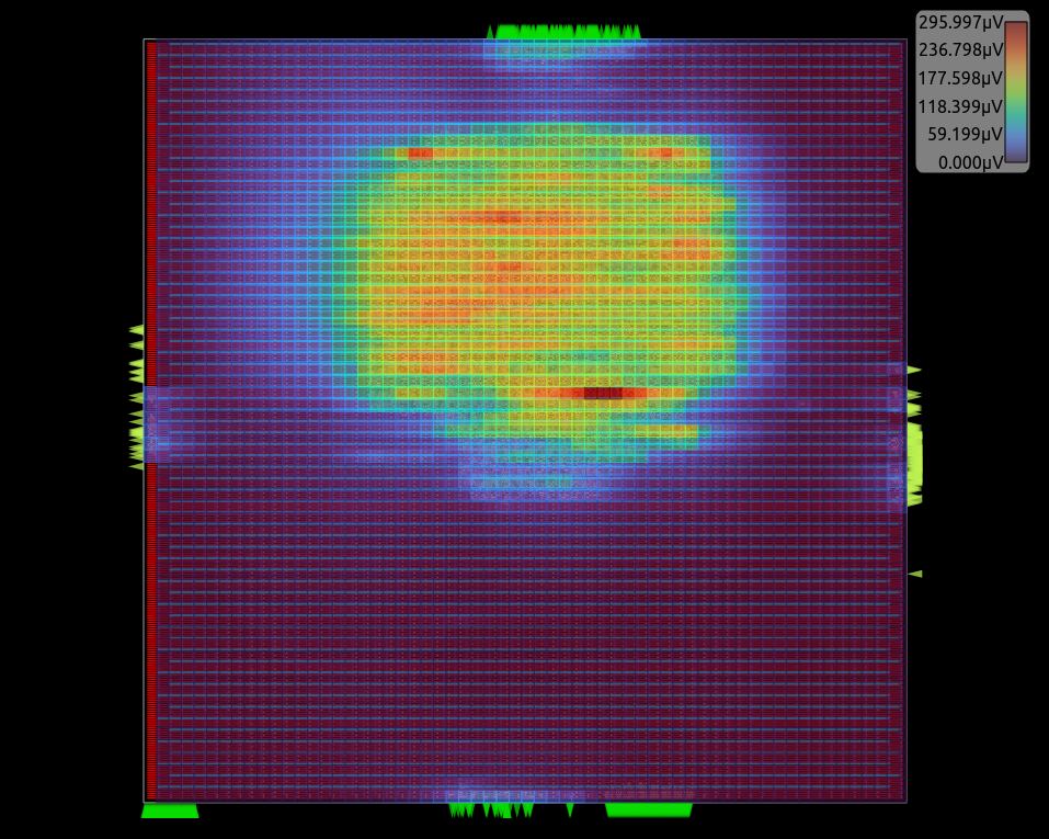
Report worst IR drop.
Report worst current density over all nodes and wire segments in the power distribution network, given a placed and PDN-synthesized design.
Check for floating PDN stripes on the power and ground nets.
Spice netlist writer for power distribution network wire segments.
Commands#
Note
Parameters in square brackets
[-param param]are optional.Parameters without square brackets
-param2 param2are required.
Analyze Power Grid#
This command analyzes power grid.
analyze_power_grid
    -net net_name
    [-corner corner]
    [-error_file error_file]
    [-voltage_file voltage_file]
    [-enable_em]
    [-em_outfile em_file]
    [-vsrc voltage_source_file]
    [-source_type FULL|BUMPS|STRAPS]
    [-allow_reuse]
Options#
Switch Name |
Description |
|---|---|
|
Name of the net to analyze, power or ground net name. |
|
Corner to use for analysis. |
|
File to write power grid error to. |
|
File to set the location of the power C4 bumps/IO pins. Vsrc_aes.loc file for an example with a description specified here. |
|
Report current per power grid segment. |
|
Write the per-segment current values into a file. This option is only available if used in combination with |
|
Write per-instance voltage into the file. |
|
Indicate the type of voltage source grid to model. FULL uses all the nodes on the top layer as voltage sources, BUMPS will model a bump grid array, and STRAPS will model power straps on the layer above the top layer. |
|
Allow the analysis to reuse a previous solution, if one exists. |
Check Power Grid#
This command checks power grid.
check_power_grid
    -net net_name
    [-floorplanning]
    [-error_file error_file]
    [-dont_require_terminals]
Options#
Switch Name |
Description |
|---|---|
|
Name of the net to analyze. Must be a power or ground net name. |
|
Ignore non-fixed instances in the power grid, this is useful during floorplanning analysis when instances may not be properly placed. |
|
File to write power grid errors to. |
|
If specified, this will skip checking if there are terminals on the net. |
Write Spice Power Grid#
This command writes the spice file for power grid.
write_pg_spice
    -net net_name
    [-vsrc vsrc_file]
    [-corner corner]
    [-source_type FULL|BUMPS|STRAPS]
    spice_file
Options#
Switch Name |
Description |
|---|---|
|
Name of the net to analyze. Must be a power or ground net name. |
|
File to set the location of the power C4 bumps/IO pins. See Vsrc_aes.loc file for an example and its description. |
|
Corner to use for analysis. |
|
Indicate the type of voltage source grid to model. FULL uses all the nodes on the top layer as voltage sources, BUMPS will model a bump grid array, and STRAPS will model power straps on the layer above the top layer. |
|
File to write spice netlist to. |
Set PDNSim Net voltage#
This command sets PDNSim net voltage.
set_pdnsim_net_voltage
    -net net_name
    -voltage volt
    [-corner corner]
Options#
Switch Name |
Description |
|---|---|
|
Name of the net to analyze. It must be a power or ground net name. |
|
Sets the voltage on a specific net. If this option is not given, the Liberty file’s voltage value is obtained from operating conditions. |
|
Corner to use this voltage. If not specified, this voltage applies to all corners. |
Set PDNSim Instance power#
This command sets PDNSim instance power. This should only be used when needing to override the computed power.
set_pdnsim_inst_power
    -inst inst_name
    -power power
    [-corner corner]
Options#
Switch Name |
Description |
|---|---|
|
Name of the instance to set the power dor. |
|
Sets the power on a specific instance. |
|
Corner to use this power. If not specified, this power applies to all corners. |
Set PDNSim Power Source Settings#
Set PDNSim power source setting.
set_pdnsim_source_settings
    [-bump_dx pitch]
    [-bump_dy pitch]
    [-bump_size size]
    [-bump_interval interval]
    [-strap_track_pitch pitch]
    [-external_resistance resistance]
Options#
Switch Name |
Description |
|---|---|
|
Set the bump pitch to decide the voltage source location. The default bump pitch is 140um. |
|
Set the bump size. The default bump size is 70um. |
|
Set the bump population interval, this is used to depopulate the bump grid to emulate signals and other power connections. The default bump pitch is 3. |
|
Sets the track pitch to use for modeling voltage sources as straps. The default is 10x. |
|
Set to model the resistance of the package or power network outside the chip/block. The default value is 0.0. |
Insert Decap Cells#
The insert_decap command inserts decap cells in the areas with the highest
IR Drop. The number of decap cells inserted will be limited to the target
capacitance defined in the -target_cap option. list_of_decap_with_cap
is a list of even size of decap master cells and their capacitances,
e.g., <cell1> <decap_of_cell1> <cell2> <decap_of_cell2> .... To insert decap
cells in the IR Drop of a specific net (power or ground) use -net <net_name>,
if not defined the default power net will be used.
To use this command, you must first execute the analyze_power_grid command
with the net to have the IR Drop information.
insert_decap -target_cap target_cap [-net net_name] -cells list_of_decap_with_cap
Options#
Switch Name |
Description |
|---|---|
|
Target capacitance to insert os decap cells. |
|
Power or ground net name. The decap cells will be inserted near the IR Drops of the net. |
|
List of even size of decap master cells and their capacitances. |
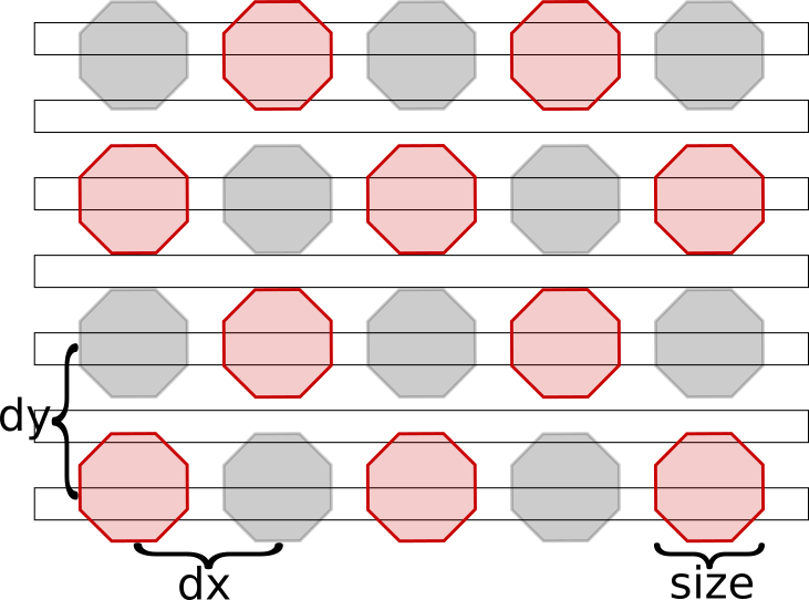
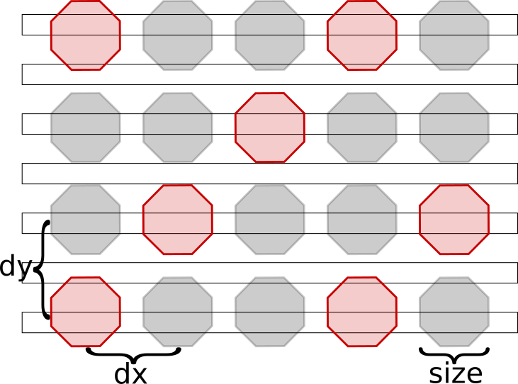
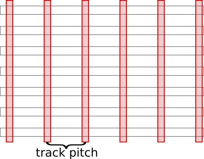
Source grid options#
The source grid models how power is going be delivered to the power grid. The image below illustrate how they can be modeled, the red elements are the source models, the black horizontal boxes represent the top metal layer of the power grid, and the gray boxes indicate these are not used in the modeling.
Bumps with 2x interval |
Bumps with 3x interval |
Straps |
Full |
|---|---|---|---|
|
|
|
|

Selectively disconnecting sources#
If you need to be able to disconnect some of the terminals in the design, such as in the case of “what-if” analysis or different chip packaging options.
This can be done by assigning PSM_DISCONNECT to a terminal or shape in a terminal will cause PDNSim to leave that object disconnected from the analysis.
# Assumes bpin is the block pin to be disconnected
odb::dbBoolProperty_create $bpin PSM_DISCONNECT 1

# Assumes box the box shape in the bpin to be disconnected
odb::dbBoolProperty_create $box PSM_DISCONNECT 1
Useful Developer Commands#
If you are a developer, you might find these useful. More details can be found in the source file or the swig file.
Command Name |
Description |
|---|---|
|
Get a reference to net name. |
Example scripts#
Example scripts demonstrating how to run PDNSim on a sample design on aes as follows:
./test/aes_test_vdd.tcl
./test/aes_test_vss.tcl
Regression tests#
There are a set of regression tests in ./test. For more information, refer to this section.
Simply run the following script:
./test/regression
Limitations#
FAQs#
Check out GitHub discussion about this tool.
References#
PDNSIM documentation
Chhabria, V.A. and Sapatnekar, S.S. (no date) The-openroad-project/pdnsim: Power Grid Analysis, GitHub. Available at: https://github.com/The-OpenROAD-Project/PDNSim (Accessed: 24 July 2023). (link)
License#
BSD 3-Clause License. See LICENSE file.